 +998 71 264 84 94
  5, Buyuk Kelazhak st, Mirzo-Ulugbek district,
Attention. Competition announced
 24.03.2026
  250
250 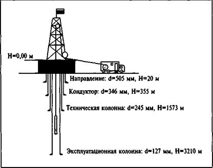
|
№ |
Name of goods and services |
number |
|
1 |
equipment and equipment (150 °C) for field and geophysical studies of oil and gas wells |
According to the technical assignment |
TECHNICAL SPECIFICATIONS
- Purpose of Acquisition
Technological upgrade and modernization of the geological industry enterprises' equipment fleet with advanced instruments and machinery.
- Project Implementation Basis
The procurement is carried out as part of the modernization and strengthening of the material and technical resources of "Uzbekgeofizika" JSC.
Source of Funds:
- Purpose
The instruments and equipment are designed for geophysical logging in open and cased holes of vertical, directional, and horizontal oil and gas wells filled with drilling fluid.
- Scope of Application
The instruments and equipment shall be applied in open holes of vertical, directional, and horizontal oil and gas wells with diameters ranging from 120 to 508 mm.
The system shall support the following survey deployment methods:
- Wireline (via geophysical cable);
- Slickline/Heavy-duty wireline (via specialized rigid geophysical cable);
- Well tractor conveyance;
- Memory mode on drill pipe (LWD/Memory logging);
- Tough Logging Conditions (TLC) / "Wet connection" technology.
Objectives (Tasks to be addressed):
- Reservoir identification in oil and gas well sections;
- Formation resistivity assessment;
- Reservoir saturation evaluation;
- Formation permeability determination;
- Rock density and porosity determination;
- Photoelectric factor (PEF) determination and mineralogical composition assessment;
- Detailed lithological differentiation;
- Determination/refinement of reservoir properties (porosity, permeability, etc.);
- Shale volume (Vsh) / clay content estimation;
- Identification of radiogeochemical anomalies;
- Determination/refinement of mineral composition;
- Identification of gas-bearing formations, gas-liquid and oil-water contacts (GWC/OWC);
- Casing collar logging (depth correlation via CCL);
- Borehole caliper measurements;
- Keyseat detection;
- Annular volume calculation;
- Well integrity monitoring (technical state control), etc.;
- Determination of true vertical depth (TVD) of productive formations;
- Wellbore trajectory control during drilling;
- Determination of formation temperature and geothermal gradient;
- Elastic moduli calculation;
- Evaluation of shear wave acoustic anisotropy (magnitude and direction).
- Main Technical Requirements
|
GENERAL TECHNICAL DATA |
|
|
Downhole module diameter, mm |
76 |
|
Wellbore diameter range, mm |
from 120 to 508 |
|
Ambient temperature range, °C |
from -10 to +150 |
|
Temperature range for tool assembly/disassembly operations, °C |
from -50 to +50 |
|
Maximum hydrostatic pressure, MPa, not less than |
100 |
|
Drilling fluid resistivity, Ohm*m, not less than |
0,02 |
|
Maximum allowable dogleg severity, °/10 m |
5 |
|
Maximum allowable axial load on downhole tools: · Tension, kN (5t); · Compression (in-well), kN (5t) |
44,48 44,48 |
|
Downhole tool supply voltage, V |
220 |
|
Downhole tool supply frequency, Hz |
50 |
|
Guaranteed operating time at maximum temperature, h, not less than |
2 |
|
Continuous operation time in logging mode, h, not less than |
10 |
|
Service life, years, not less than |
5 |
5.1. Downhole Tools
|
Multi-probe Combined Laterolog Tool (5-probe Array Laterolog) |
||
|
PURPOSE: Designed to measure the apparent electrical resistivity (ra) of formations using five focused laterolog probes. |
||
|
APPLICATION: Used in open holes of oil and gas wells filled with water-based drilling fluid. |
||
|
OBJECTIVES: Ø Reservoir identification in oil and gas well sections; Ø Formation resistivity assessment; Ø Reservoir saturation evaluation. |
||
|
MEASURED PARAMETERS |
Measurement range |
Primary error |
|
R1 apparent electrical resistivity |
0,1¸5000 Ohm·m |
±10%, for 0,1˂ra ˂1 Ohm·m ±5%, for 1˂ra ˂5000 Ohm·m ±10%, for 5000˂ra ˂10000 Ohm·m ±20%, for ra ˃10000 Ohm·m |
|
R2 apparent electrical resistivity |
0,1¸10000 Ohm·m |
|
|
R3 apparent electrical resistivity |
0,1¸40000 Ohm·m |
|
|
R4 apparent electrical resistivity |
||
|
R5 apparent electrical resistivity |
||
|
GENERAL TECHNICAL DATA |
||
|
Assembly length, mm |
8300 |
not more than |
|
Total weight, kg |
150 |
not more than |
|
Logging speed, m/h |
800-1000 |
|
|
Combinability |
feed-through |
|
|
In-hole position |
centered |
|
|
Independent Arm Micro-Method and Micro-Laterolog Tool (MC + MLL) |
||
|
PURPOSE: Designed for measuring the apparent electrical resistivity (ra) of formations penetrated by the wellbore using Micro-Log (MC) and Micro-Laterolog (MLL) methods, with simultaneous borehole diameter measurement. |
||
|
APPLICATION: Used in open holes of oil and gas wells filled with water-based drilling fluid. |
||
|
OBJECTIVES: Ø Reservoir identification in oil and gas well sections; Ø Assessment of the formation resistivity in the invaded zone. |
||
|
The MC and MLL measuring probes are mounted on two pads pressed against the borehole wall by a controllable linkage system. The MC pad houses a gradient micro-probe (A0.025M0.025N or equivalent) and a potential micro-probe (A0.05M or equivalent). The MLL measuring probe is a three-electrode system. Current focusing for the MLL probe is achieved through automatic potential regulation of the probe electrodes.
|
||
|
MEASURED PARAMETERS |
Measurement range |
Primary error, % |
|
Apparent resistivity (ra) of gradient and potential micro-probes |
from 0.1 to 50 Ohm·m at a ρa/ρm ratio not exceeding 500 |
±(5+7.5 Ohm·m /ra) % |
|
Apparent resistivity (ra) of the MLL probe |
from 0.5 to 800 Ohm·m at a ρa/ρm ratio not exceeding 1500 |
±(5+40 Ohm·m /ra) % |
|
Borehole diameter (dh) |
110¸400 mm |
± 5 % |
|
GENERAL TECHNICAL DATA |
||
|
Length, mm · Overall length · Assembly length |
4740 4670 |
not more than |
|
Tool diameter, mm |
90 |
not more than |
|
Total weight, kg |
110 |
not more than |
|
Drive control |
Multi-action, surface-controlled |
|
|
Logging speed, m/h |
Up to 1000 |
|
|
Combinability |
Bottom-only |
|
|
In-hole position |
Pad-pressed against the borehole wall |
|
|
Five-Probe Induction Logging Tool (5-IL) |
|||||||||||
|
PURPOSE: Designed for induction logging using a suite of five probes with varying depths of investigation, with simultaneous registration of active and reactive components of the apparent conductivity for each probe. Additionally, the SP (Spontaneous Potential) signal is transmitted in analog form via the 3rd cable conductor. |
|||||||||||
|
APPLICATION: Used in open holes of oil and gas wells filled with water-based or oil-based drilling fluids. |
|||||||||||
|
OBJECTIVES: Ø Reservoir identification in oil and gas well sections; Ø Formation resistivity assessment; Ø Reservoir saturation evaluation. |
|||||||||||
|
The tool comprises five three-coil induction probes: 3I0.3, 3I0.5, 3I0.85, 3I1.26, and 3I2.05. All probes share a common receiver coil and a single measurement circuit, operating at a frequency of 100 kHz. |
|||||||||||
|
MEASURED PARAMETERS |
Measurement range |
Primary error |
|||||||||
|
Probe |
Channel |
sa, mS/m |
ra, Ohm·m |
± (0.03´sa +1 mS/m) |
|||||||
|
3I0.3 |
Active |
3¸2000 |
0.3¸300 |
||||||||
|
Reactive |
3¸1500 |
0.3¸15 |
|||||||||
|
3I0.5 |
Active |
3¸1500 |
0.3¸300 |
||||||||
|
Reactive |
3¸1500 |
0.3¸20 |
|||||||||
|
3I0.85 |
Active |
3¸1000 |
0.3¸300 |
||||||||
|
Reactive |
3¸1000 |
0.3¸30 |
|||||||||
|
3I1.26 |
Active |
3¸500 |
0.6¸300 |
||||||||
|
Reactive |
3¸1000 |
0.3¸35 |
|||||||||
|
3I2.05 |
Active |
3¸300 |
1.0¸300 |
||||||||
|
Reactive |
3¸700 |
0.3¸45 |
|||||||||
|
Probe sensitivity |
0.5 mS/m |
||||||||||
|
Probe resolution |
3I0.3 |
3I0.5 |
3I0.85 |
3I1.26 |
3I2.05 |
||||||
|
Vertical resolution Н0.5, m |
0.35 |
0.61 |
1.03 |
1.54 |
2.50 |
||||||
|
Investigation radius R0.5, m |
0.4 |
0.72 |
1.23 |
1.82 |
2.97 |
||||||
|
GENERAL TECHNICAL DATA |
|||||||||||
|
Length, mm · Overall length · Assembly length |
5500 5300 |
not more than |
|||||||||
|
Total weight, kg |
95 |
not more than |
|||||||||
|
Logging speed, m/h |
Up to 1500 |
|
|||||||||
|
Combinability |
Feed-through |
||||||||||
|
In-hole position |
With stand-offs |
||||||||||
|
Combined Radioactive Logging Tool |
||
|
PURPOSE: Designed to measure the water-saturated porosity of formations using the Neutron Gamma Logging (NGL) method and the Dual-Spacing (Compensated) Thermal Neutron-Neutron Logging (2NNKt) method. |
||
|
APPLICATION: Used for the survey of open and cased-hole oil and gas wells filled with any type of drilling fluid. |
||
|
OBJECTIVES: Ø Correlation of well sections and lithological variations; Ø Detailed lithological subdivision (zonation); Ø Identification of gas-bearing formations, gas-liquid (GOC) and oil-water (OWC) contacts; Ø Determination of formation porosity coefficient; Ø Determination of gas saturation coefficient. |
||
|
The NGL and 2NNKt probe measurement assemblies consist of a scintillation detector with a PMT (NGL probe), two helium thermal neutron detectors (2NNKt probe), and a fast neutron capsule source (Pu-Be, with a yield of 5×10⁶ to 2×10⁷ n/s), which is shared by both measurement assemblies.
|
||
|
MEASURED PARAMETERS |
Measurement range |
Primary error, % |
|
Water-saturated porosity by CNL |
1¸40 % |
4.2+2.3(40/Kp-1), % |
|
Water-saturated porosity by NGL |
1¸40 % |
4.2+2.3(40/Kp-1), % |
|
Average thermal neutron count rate in water, at least: · Near probe (detector) · Far probe (detector) |
30000 cpm 1500 cpm |
|
|
NGL probe sensitivity, at least: |
4000 (cpm)/ r.u. |
|
|
GENERAL TECHNICAL DATA |
||
|
Length, mm · Overall length · Assembly length |
5140 4856 |
not more than |
|
Total weight, kg |
95 |
not more than |
|
Logging speed, m/h · In terrigenous sections · In carbonate sections |
250¸400 400¸800 |
|
|
Combinability |
Feed-through |
|
|
In-hole position |
Pad-pressed or free-hanging |
|
|
Spectral Gamma Ray (SGR) tool |
||
|
PURPOSE: Designed for the measurement of the mass concentrations of naturally occurring radioactive elements (NORM) in rock formations: thorium (Th), uranium (U), and potassium (K). |
||
|
APPLICATION: used for surveys in both open and cased hole environments of oil and gas wells, regardless of the wellbore fluid type. |
||
|
OBJECTIVES: Ø Wellbore correlation and identification of lithological changes; Ø Detailed lithological differentiation; shale volume (clay content) estimation; Ø Stratigraphic studies; Ø Determination and refinement of petrophysical properties; Ø Determination and refinement of the mineral composition of rocks. |
||
|
The probe assembly comprises a scintillation detector and a photomultiplier tube (PMT). |
||
|
MEASURED PARAMETERS |
Measurement range |
Error |
|
Thorium (Th) mass concentration |
0.5¸200×10-4 % |
±1,5∙10-4 absolute, 10% relative at THOR>15∙10-4 % |
|
Uranium (U) mass concentration |
0.5¸200×10-4 % |
±1,5∙10-4 absolute, 10% relative at URAN>15∙10-4 % |
|
Potassium (K) mass concentration |
0.1¸20 % |
±0.3 % absolute 10% relative at POTA> 3% |
|
Sensitivity |
not less than 1,500 (cpm)/µR/h |
|
|
GENERAL TECHNICAL DATA |
||
|
Length, mm · Overall length · Assembly length |
2500 2250 |
not more than |
|
Total weight, kg |
80 |
not more than |
|
Nominal borehole diameter, mm |
from 120 to 350 |
|
|
Logging speed, m/h: - In high-activity formations (JGR >5 µR/h) General surveys Detailed surveys - In low-activity formations (JGR >5 µR/h) General surveys Detailed surveys |
140¸180 80¸120
110¸150 60¸100 |
|
|
Combinability |
Feed-through |
|
|
In-hole position |
free-hanging |
|
|
|
|
||||||||||||||||||||||||||||||||||||||||||||||||||||||||||||||||||||||||||||||||||||||||||||||||||||||||||||||||||||||||||||||||||||||||||||||||||||||||||||||||||||||||||||||||||||||||||||||||||||||||||||||||||||||||||||||||||||||||||||||||||||||||||||||||||||||||||||||||||||||||||||||||||||||||||||||||||||||||||||||||||||||||||||||||||||||||||||||||||||||||||||||||||||||||||||||||||||||||||||||||||||||||||||||||||||||||||||||||||||||||||||||||||||||||||||||||||||||||||||||||||||||||||||||||||||||||||||||||||||||||||||||||||||||||||||||||||||||||||||||||||||||||||||||||||||||||||||||||||||||||||||||||||||||||||||||||||||||||||||||||
5.2. Auxiliary equipment
5.3. Metrological Equipment
6. Scope of Supply Each downhole tool and equipment set must include a set of spare parts, tools, and accessories (SPTA).
7. Installation, Commissioning, and Training Requirements The Supplier shall provide information on equipment operating costs, including the post-warranty period. The Supplier shall provide energy-efficient equipment. Additional Requirements: - Provision of technical descriptions, operation, and maintenance manuals in both Russian and English, in electronic and hard copy formats; - Training of the Customer’s personnel (8 specialists) on equipment operation, maintenance, troubleshooting, and repair; - Supervision of installation (supervision) shall be carried out by the Supplier; - Commissioning works shall be performed by the Supplier with the direct participation of the Customer at the Customer's site. 8. Pre-shipment Inspection Requirements Pre-shipment inspection (PSI) of the Goods shall be carried out at the Supplier's facility with the participation of 2 (two) of the Consignee's specialists. 9. Destination and Insurance Consignee: "Amirobod kon-geofizika ekspeditsiyasi" branch of "Uzbekgeofizika" JSC. 10. Dimensions, Packaging, and Shipping Requirements The packaging of the goods must meet all necessary storage and transportation requirements, ensuring the protection of the goods from environmental and mechanical impacts during transport, loading, and unloading. Loose parts that form an integral part of the goods may be secured separately within the packaging to avoid damage during transit. The packaging must be properly labeled. Labeling must be clear, made with indelible ink, in Russian and/or English. Packaging must ensure full protection against damage and corrosion during transportation. The packaging shall be designed for handling by forklifts, cranes, and manual labor. 11. Newness Requirements The Goods must be new (unused, non-refurbished) and manufactured no earlier than 2026.
12. Quality Requirements The quality of the Goods must comply with the requirements of international standards ISO 9001, 9002, and later modifications, supported by relevant certificates. The quality of the Goods must meet the established standards and technical specifications (TS) of the manufacturer and be confirmed by Quality Certificates and Factory Acceptance Test (FAT) reports issued by the manufacturer. The Goods and their materials must undergo testing at the metrological center of the Seller or its sub-suppliers in accordance with the standards applicable to the Goods and their materials. 13. Delivery Terms Delivery shall be carried out by air, road, or rail to the customs warehouse in Bukhara on DAP-Bukhara terms (Incoterms 2020). The Goods must be shipped within 360 calendar days from the date of contract conclusion. 14. Delivery and Acceptance Procedure Acceptance regarding the integrity and completeness of the delivered equipment shall be performed during customs inspection at the destination. The Supplier has the right to be present and participate in the customs inspection. Quantitative acceptance — performed by the Customer in accordance with the bill of lading, packing list, invoice, labeling, and Contract Specification, followed by the execution of a Goods Acceptance Certificate. To accept the results of the work (services), the Customer reserves the right to establish an Acceptance Commission in the prescribed manner. Upon presentation of the goods (works, services) to the Commission, the set of documentation developed by the Contractor shall be submitted, including the list and requirements for documentation according to the regulations in force in the Republic of Uzbekistan. The Supplier shall ship the Goods with the following documents: Waybill (consignment note) issued to the Customer, specifying the destination, Customer name, invoice number/date, and contract number/date; Commercial Invoice; Packing List; Certificate of Origin; Manufacturer’s Quality Certificate; Certificate of Conformity (if the goods are subject to mandatory certification); Equipment Passport; Operation and Repair Manual; Export Customs Declaration; Set of technical/operational documentation (in English and/or Russian).
15. Warranty Obligations The warranty period for the operation of the goods shall be at least 24 months from the date of commissioning. The Supplier guarantees that the end-of-support date (including the equipment life cycle) shall be no earlier than 5 years from the date of commissioning. The Supplier guarantees post-warranty service for the equipment (after the initial 5-year period). Equipment support implies the availability of maintenance and repair services for all blocks and components of hardware and software. The Supplier guarantees that the date for ending order acceptance, production, and supply of individual boards and modules (EOM — end of market for expansion) shall be no earlier than 5 years from the date of the hardware supply contract conclusion. The Supplier guarantees the quality of the goods in accordance with international and/or other similar standards. In the event of a breakdown or detection of a defect during the warranty period, the Supplier is obliged to rectify the defect or provide an adequate replacement at its own expense within 60 days.
|
|||||||||||||||||||||||||||||||||||||||||||||||||||||||||||||||||||||||||||||||||||||||||||||||||||||||||||||||||||||||||||||||||||||||||||||||||||||||||||||||||||||||||||||||||||||||||||||||||||||||||||||||||||||||||||||||||||||||||||||||||||||||||||||||||||||||||||||||||||||||||||||||||||||||||||||||||||||||||||||||||||||||||||||||||||||||||||||||||||||||||||||||||||||||||||||||||||||||||||||||||||||||||||||||||||||||||||||||||||||||||||||||||||||||||||||||||||||||||||||||||||||||||||||||||||||||||||||||||||||||||||||||||||||||||||||||||||||||||||||||||||||||||||||||||||||||||||||||||||||||||||||||||||||||||||||||||||||||||||||||||
Commercial offers should be sent to the
Chairman of the Board of JSC "Uzbekgeofizika" R.A. Yusupzhonov by e-mail kancelyariya@uzbekgeofizika.uz, uzgeoinfo@mail.ru
Additional information by phone: 88 247 22 20. Duration of submission of commercial proposals is 7 calendar days from the date of publication.


